Nsound Filters
Nsound currently provides two kinds of filters:
Finite Impulse Response (FIR)
Infinite Impulse Response (IIR)
Nsound provides both FIR and IIR filters for the types below:
Low Pass
High Pass
Band Pass
Band Reject (Or Notch filter)
FIR Filters
FIR filters are well behaved at all frequencies, they have symmetric phase distortion and are relatively computationally expensive.
Currently, Nsound designs FIR filters using a windowed sinc function and a Blackman window. See “DSP for Scientists and Engineer”, Chapter 16, equation 16-4.
Some of the basic documentation
- FilterLowPassFIR(sample_rate, n_order, fc)
- FilterHighPassFIR(sample_rate, n_order, fc)
- FilterBandPassFIR(sample_rate, n_order, fc_low, fc_high)
- FilterBandRejectFIR(sample_rate, n_order, fc_low, fc_high)
- sample_rate
The number of samples per second.
- n_order
The size of the filter kernel, the larger the order, the stronger the the rejection ouside of the pass band.
- fc
The filter cut off frequency in Hz.
- fc_low
The lower filter cut off frequency in Hz
- fc_high
The high filter cut off frequency in Hz
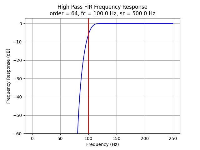
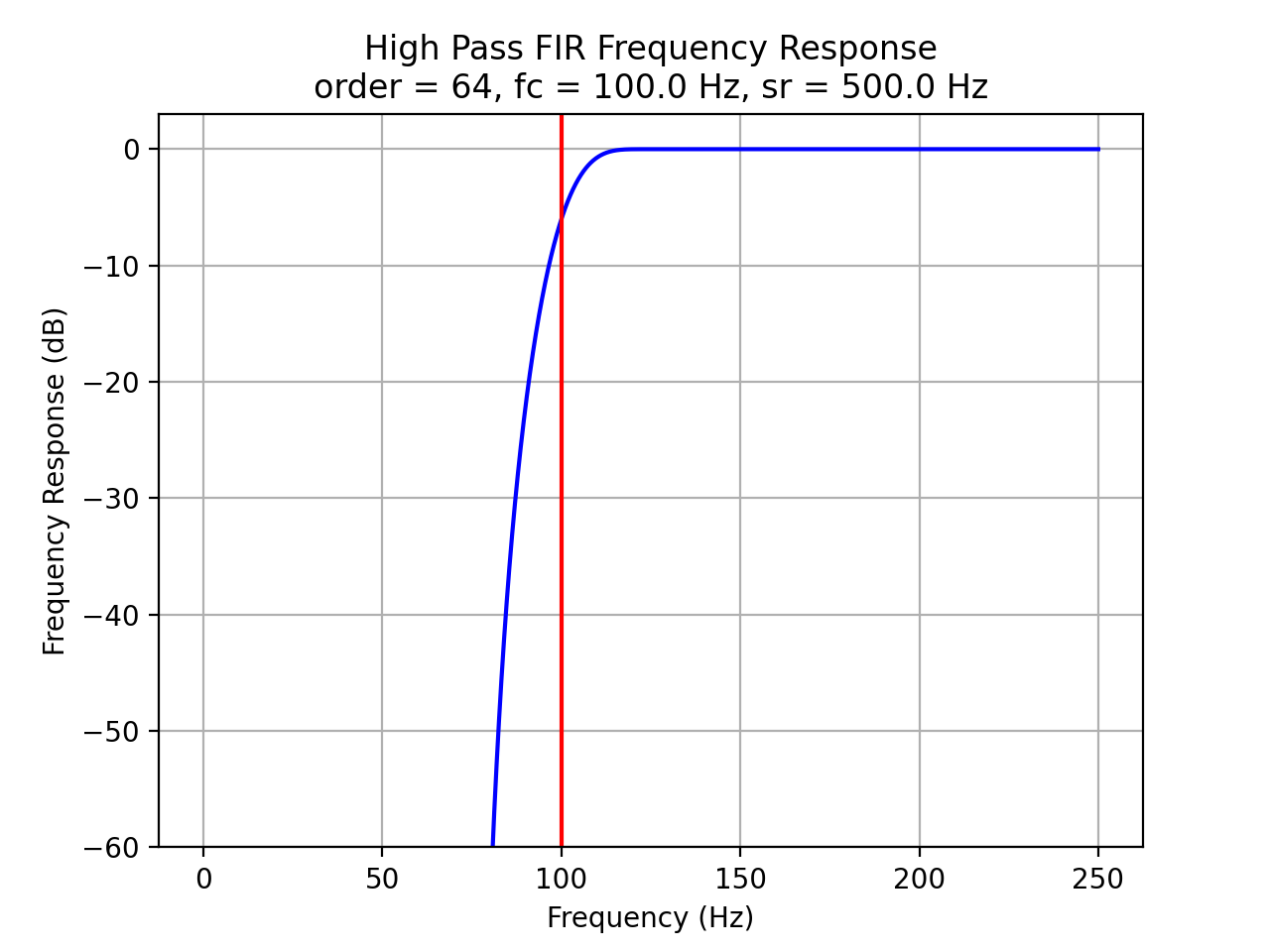
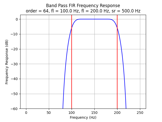
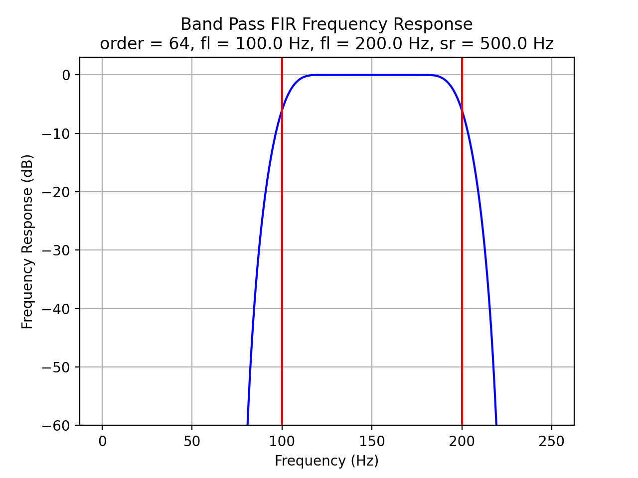
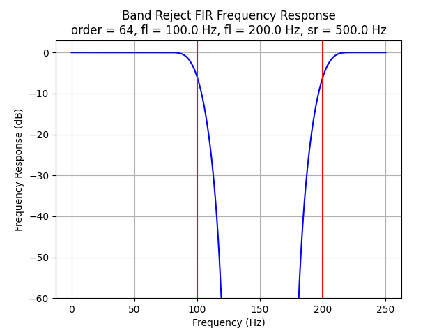
FIR Filter Frequency Response
Frequency responses for FIR filters:
import Nsound as ns

f1 = ns.FilterLowPassFIR(500.0, 64, 100.0)
f2 = ns.FilterHighPassFIR(500.0, 64, 100.0)
f3 = ns.FilterBandPassFIR(500.0, 64, 100.0, 200.0)
f4 = ns.FilterBandRejectFIR(500.0, 64, 100.0, 200.0)

f1.plot()
f2.plot()
f3.plot()
f4.plot()

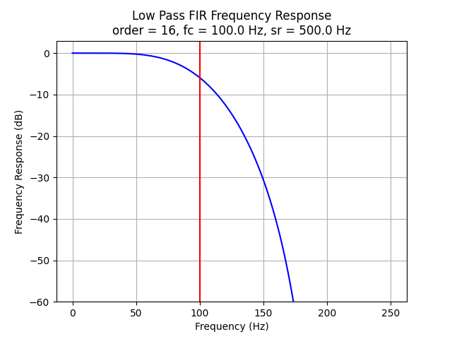
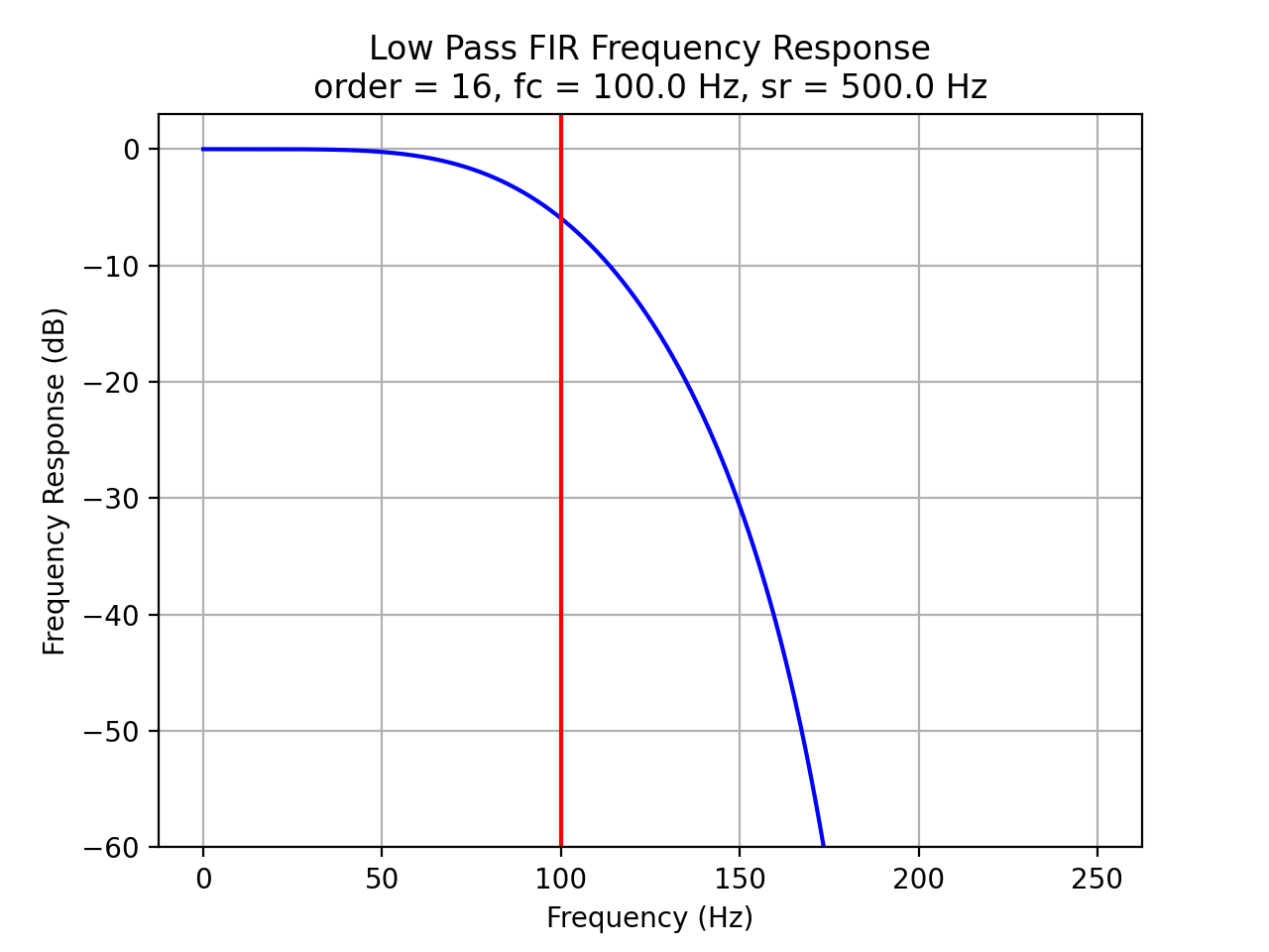
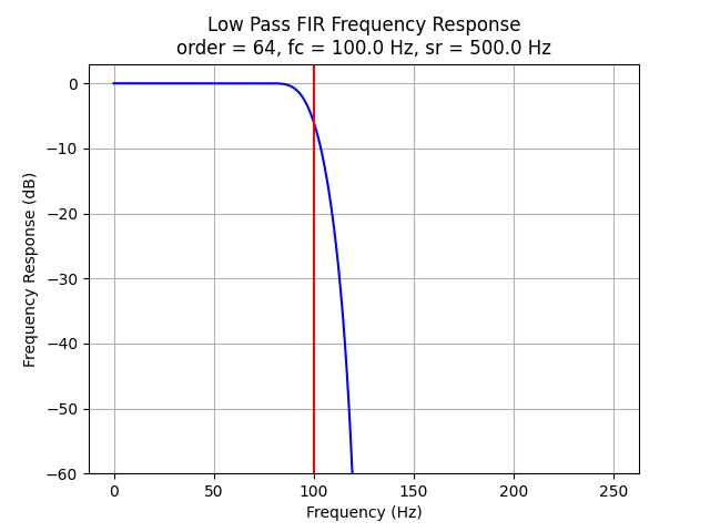
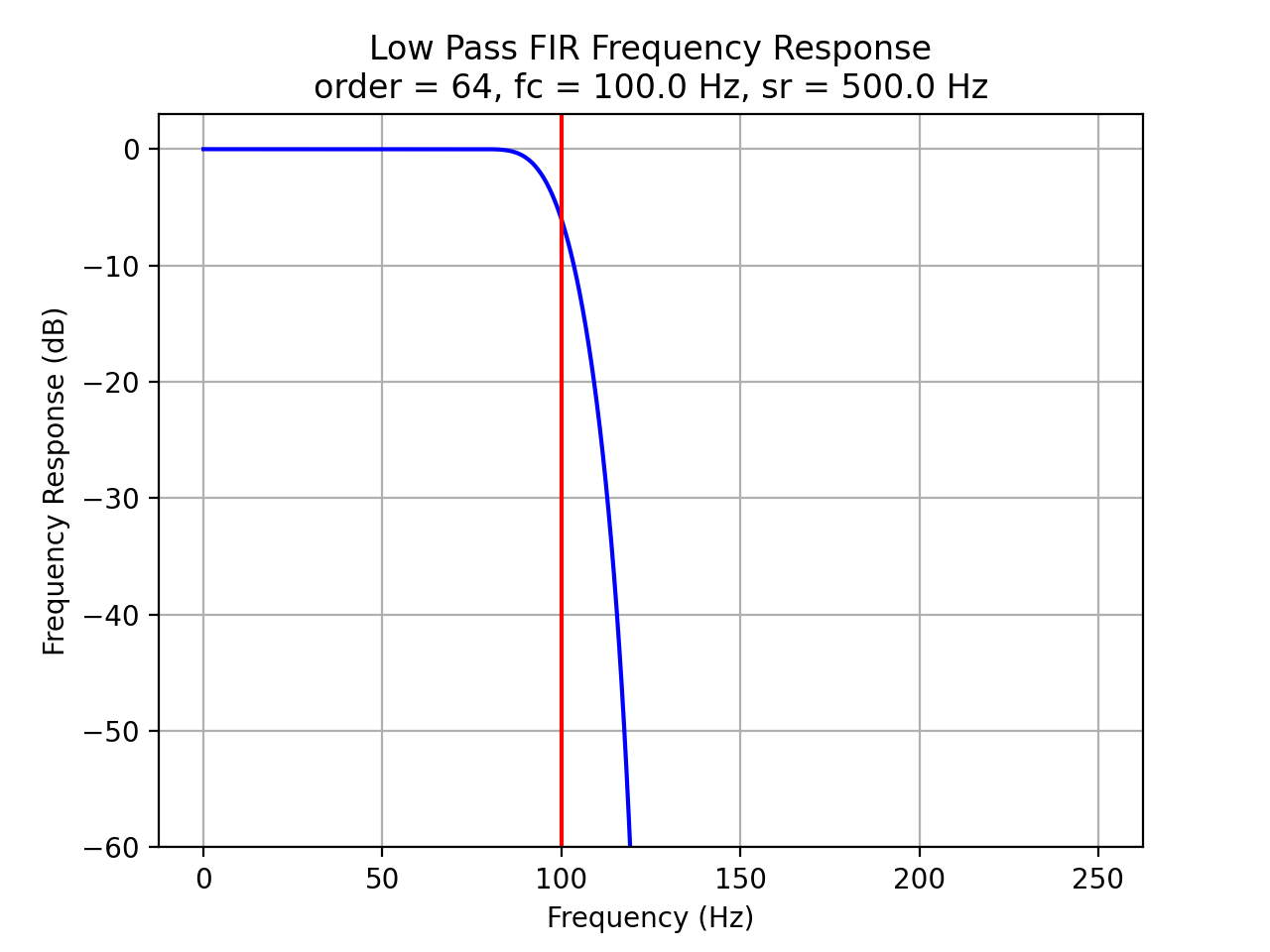
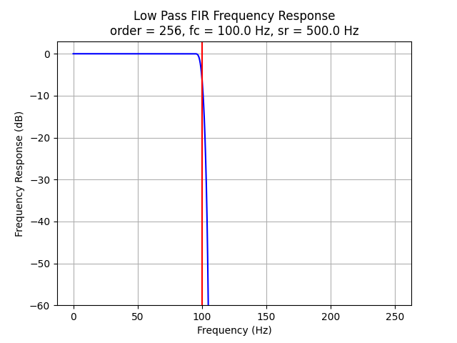
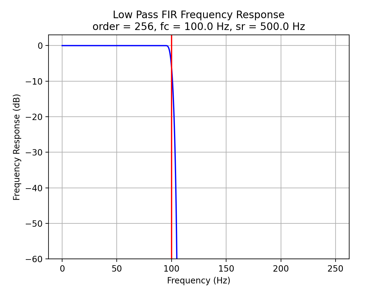
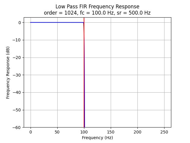
FIR Filter Frequency Response vs Filter Order
The plots below demonstrate the effects of filter order.
import Nsound as ns

f1 = ns.FilterLowPassFIR(500.0,   16, 100.0)
f2 = ns.FilterLowPassFIR(500.0,   64, 100.0)
f3 = ns.FilterLowPassFIR(500.0,  256, 100.0)
f4 = ns.FilterLowPassFIR(500.0, 1024, 100.0)

f1.plot()
f2.plot()
f3.plot()
f4.plot()


IIR Filters
IIR filters are not stable for all orders and cut off frequencies, they have asymmetrical phase distortion, but they are computationally inexpensive compared to FIR designs (because they perform far fewer multiplications).
Currently, Nsound designs IIR filters using Chebyshev type 1, ripples in the pass band. See “DSP for Scientists and Engineers”, Chapter 20, Table 20-4, 20-5. If the ripple percent parameter is set to 0.0, then the filter is maximally flat and equilavent to a Butterworth filter. Consider using 0.005 (0.5%) as the ripple percent, this acchives a sharper roll off with little ripple.
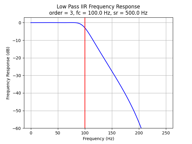
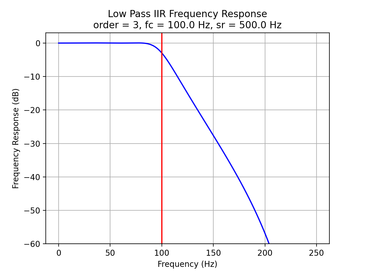
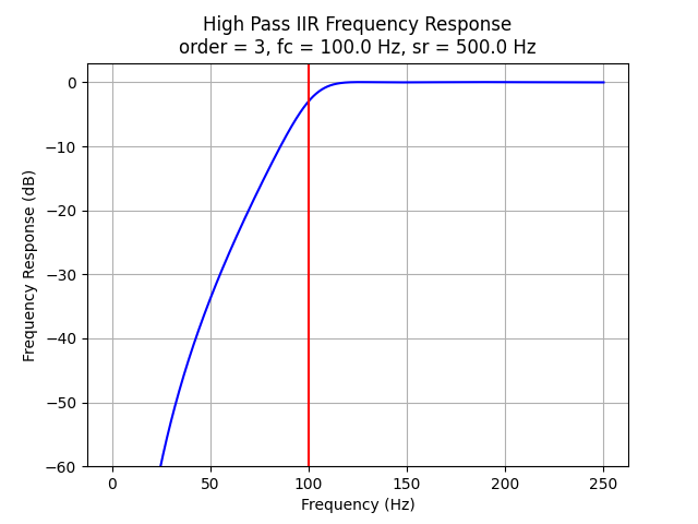
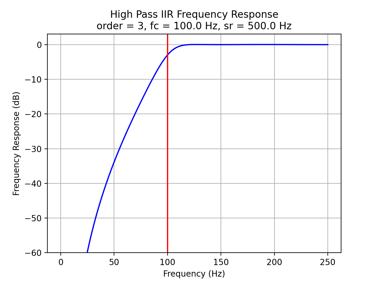
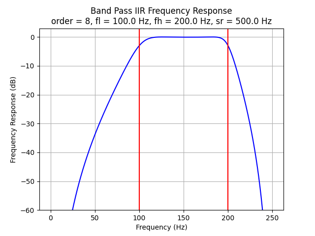
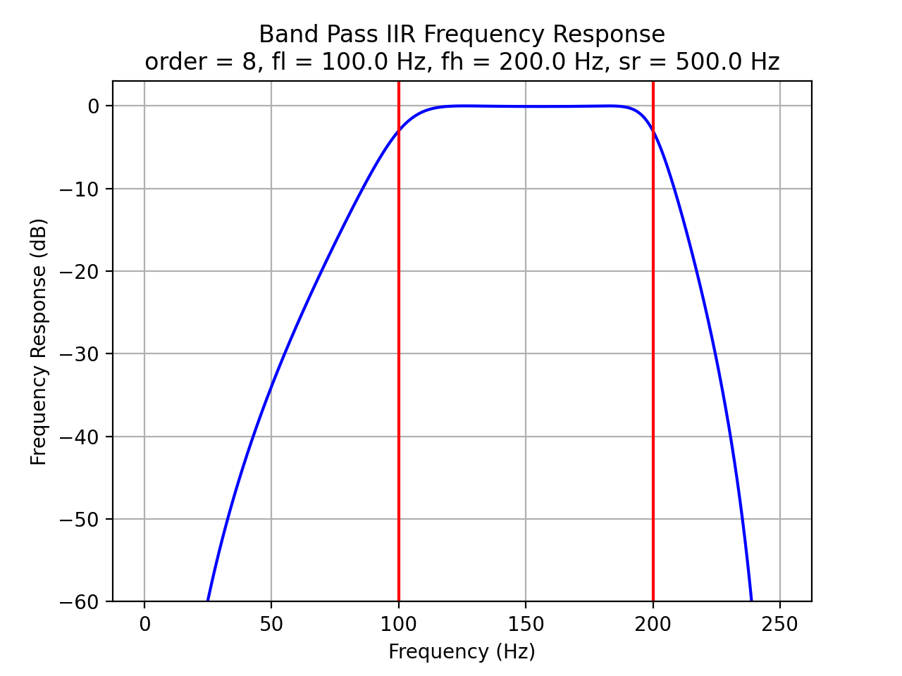
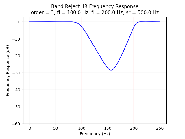
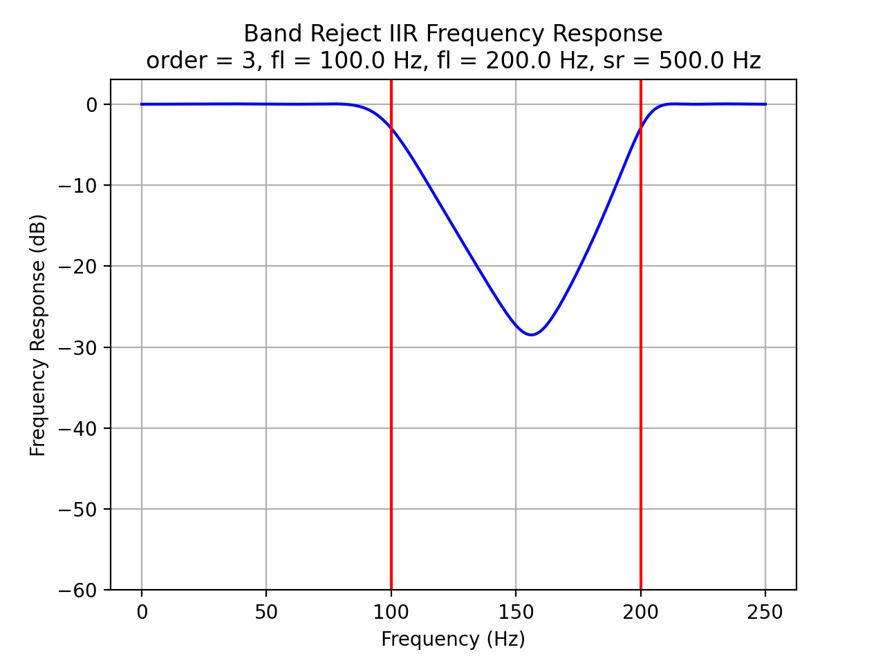
IIR Filter Frequency Response
Frequency responses for IIR filters:
import Nsound as ns

ripple = 0.005

f1 = ns.FilterLowPassIIR(500.0, 4, 100.0, ripple)
f2 = ns.FilterHighPassIIR(500.0, 4, 100.0, ripple)
f3 = ns.FilterBandPassIIR(500.0, 4, 100.0, 200.0, ripple)
f4 = ns.FilterBandRejectIIR(500.0, 4, 100.0, 200.0, ripple)

f1.plot()
f2.plot()
f3.plot()
f4.plot()


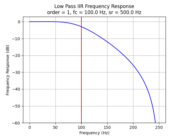
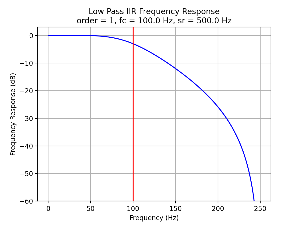
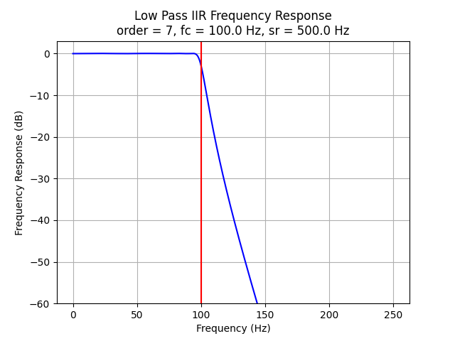
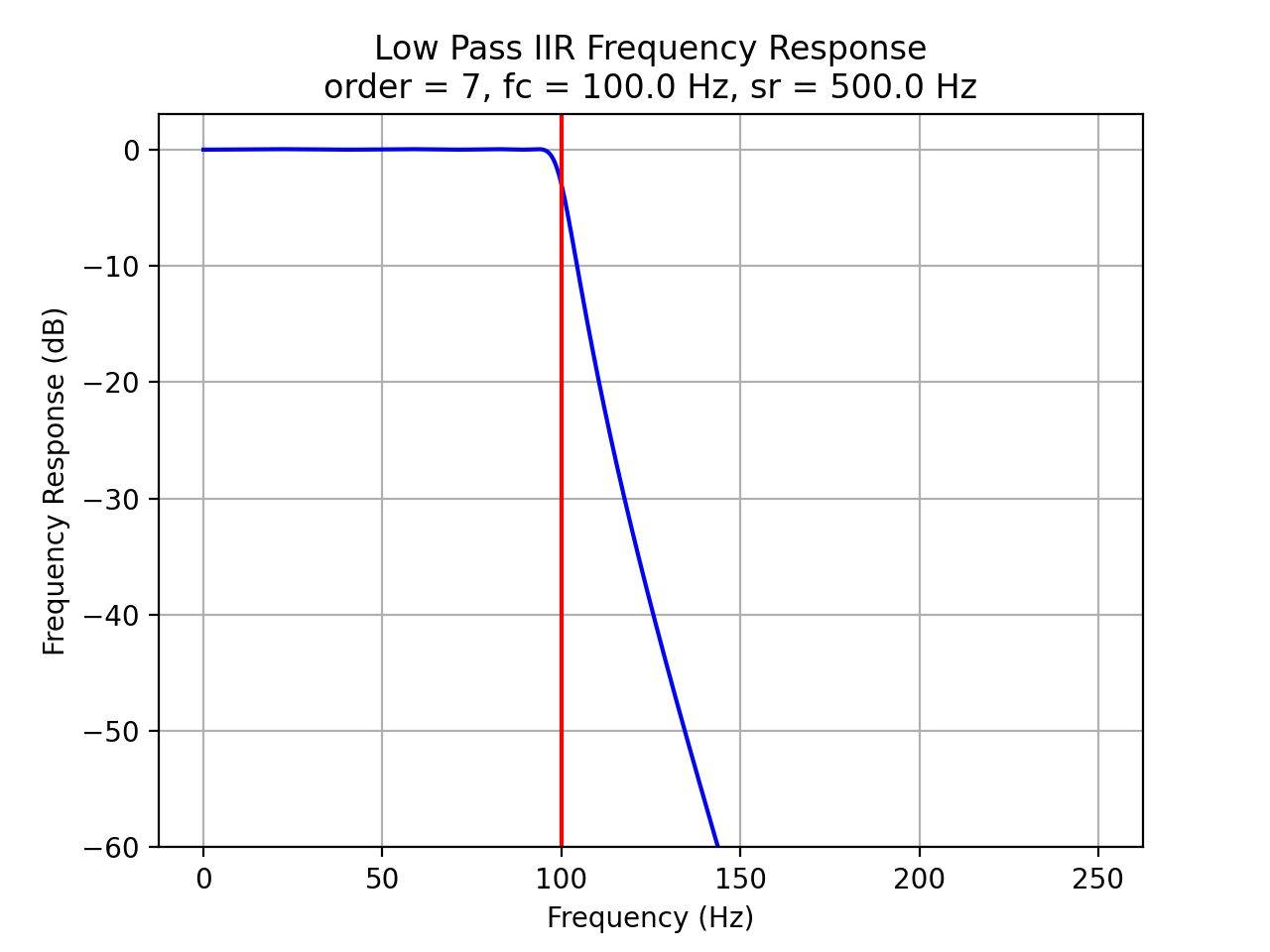
IIR Filter Frequency Response vs Filter Order
The plots below demonstrate the effects of filter order.
import Nsound as ns

ripple = 0.005

f1 = ns.FilterLowPassIIR(500.0,  2, 100.0, ripple)
f2 = ns.FilterLowPassIIR(500.0,  4, 100.0, ripple)
f3 = ns.FilterLowPassIIR(500.0,  8, 100.0, ripple)
f4 = ns.FilterLowPassIIR(500.0, 16, 100.0, ripple)

f1.plot()
f2.plot()
f3.plot()
f4.plot()


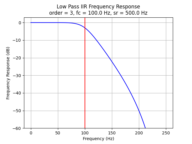
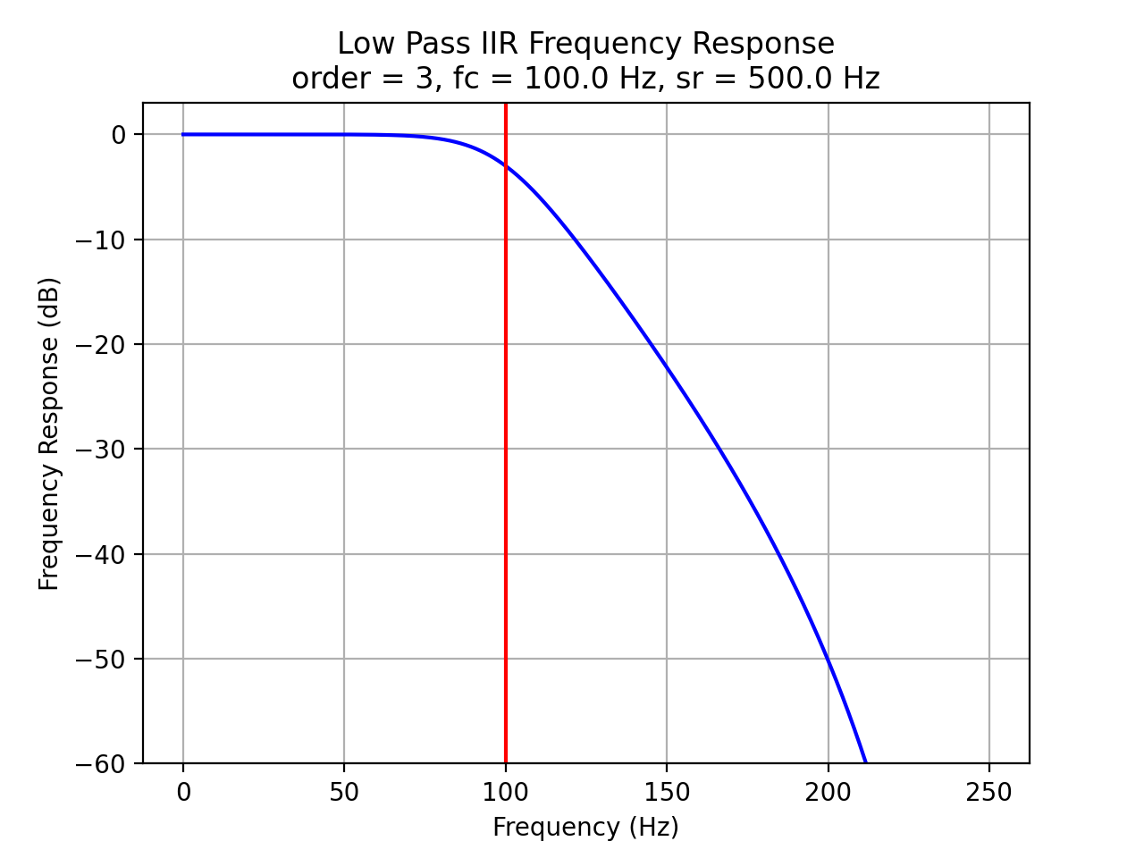
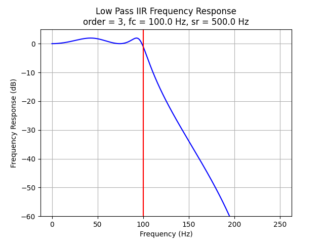
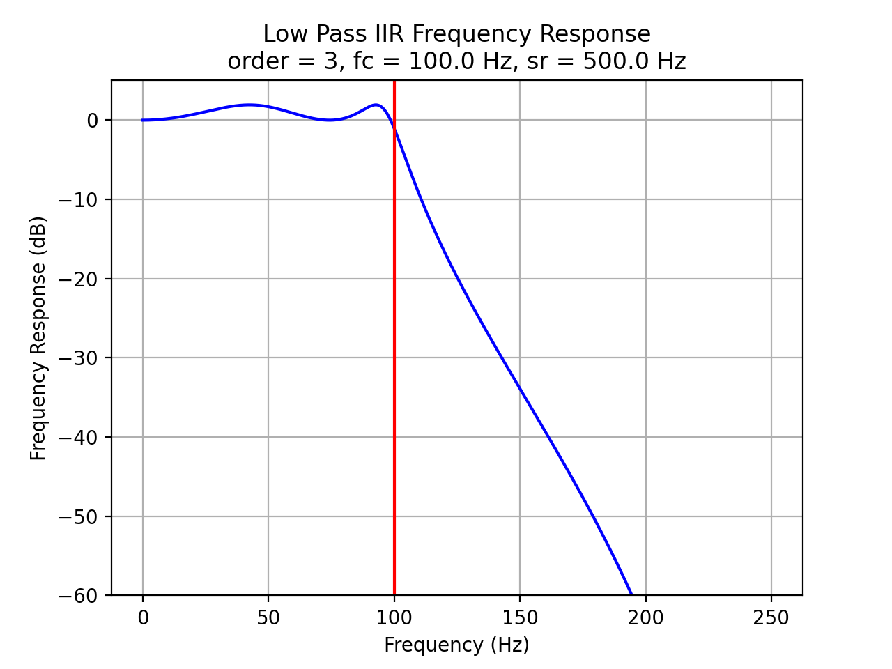
IIR Filter Frequency Response vs Ripple Percent
The plots below demonstrate the effects of filter order.
import Nsound as ns

f1 = ns.FilterLowPassIIR(500.0,  4, 100.0, 0.000)
f2 = ns.FilterLowPassIIR(500.0,  4, 100.0, 0.005)
f3 = ns.FilterLowPassIIR(500.0,  4, 100.0, 0.010)
f4 = ns.FilterLowPassIIR(500.0,  4, 100.0, 0.200)

f1.plot()
f2.plot()
f3.plot()
f4.plot()


